UÇAK TÜRBİN YAKIT SİSTEMİ EĞİTİM SETİ (5 TANK – 2 MOTOR)

FCU 100V UÇAK TÜRBİN YAKIT SİSTEMİ EĞİTİM SETİ (5 TANK – 2 MOTOR)

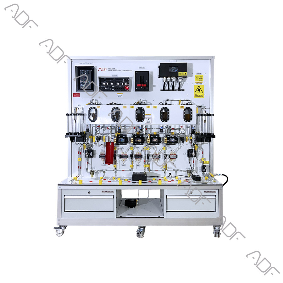
Designed to represent a complete aircraft fuel system, Model FCU – 100 Turbine Fuel System Training Set enables trainees to learn the essentials of fuel system components and how these components are linked to each other in a typical aircraft fuel system.
This trainer includes a capacitance fuel system that shows non-linear fuel quantity indications with multiple probes set at various angles. It comes fully plumbed and with a wing tank.
This completely functional fuel system consists of a fuel management panel, fuel transfer system and capacitance fuel quantity indicating system. It also contains an instructor’s panel that makes it possible to add faults to conduct troubleshooting training.
The fuel system panel features fuel quantity indicators, a fuel transfer selector valve, fuel transfer and low fuel warning lights, fuel pressure and flow indicators and complete fuel system drawings.
This system contains, engine driven fuel pump, screen, fuel filter, fuel control unit, system sensors, fuel dispenser system turbine fuel nozzle inside a clear enclosed container etc.

Features:

  • Understand fundamentals of aircraft fuel system and its components.
  • Fully functional and configured like a typical aircraft fuel system.
  • Aircraft fuel system can run automatically and manually.
  • Fuel tanks are automatically filled and when tank is full system is automatically be shut off.
  • The control of the fuel that flows to combustion chamber can be observed using the throttle lever.
  • Some of Trainer Functions
    • Mode selector auto/manual function
    • Cross feed function
    • Pump’s fault function
    • ECAM functions
    • Single chime functions
    • Master caution functions
    • Master warning functions
  • Some of Trainer Processes
    • Fuel transfer process
    • Refueling process
    • Defueling process
    • Bonding process
  • Some of Trainer Cases
    • Inner cell full
    • Slat extended
    • No engine starts
    • Center tank low level
    • Wing tank full
  • Fuel dispenser unit and its equipment
  • Bonding equipment
  • Aircraft fire scenario is simulated.
  • Fuel tanks be manually drained for maintenance.
  • Fuel tanks have transparent window in order to observe fuel filling and refilling.
  • Combustion chambers is transparent.
  • Tanks are able to manually or automatically cross-fit.
  • The hose and tubes used in the trainer are labeled according to aviation standards.
  • Wirings on the trainer are connected via terminals.
  • Wires have clear identification labels for each wire.
  • All wires are coded and labeled for troubleshooting.
  • All required hoses and pipes
  • Instructor’s panel for Fault & simulation Insertion panel (Independent unit)
  • Components:
  • Fuel Control Unit
  • Five (5) pieces fuel tank (2 inner, 2 outers, 1 center)
  • Six (6) pieces fuel pump
  • Three (3) Level control switches
  • Two (2) Combustion chamber
  • Engine no: 1 Combustion chamber
  • Engine no: 2 Combustion chamber
  • Two (2) Nozzle
  • Throttle lever,
    • Dual quadrants
    • Dual engine start panel
  • Two transfer valves
  • Suction Valve
  • Fuel filter
  • Cross feed control valve
  • Fuel System Pressure sensor for each line
  • Fuel Level sensor for each tank
  • Fuel System Flow Sensor
  • Fuel temp sensor
  • Hi level sensor for each tank
  • Two Engine Shut-Off Valve
  • Three (3) manuals drain valve
  • Check valves
  • Refueling panel
    • Left hi level
    • Center hi level
    • Right hi level
    • Refuel valves open function
    • Refuel valves norm function
    • Refuel valves shut function
    • Refuel mode selector SW
    • Transfer valve indicator
    • Test SW
    • END indicator
  • Two (2) Refuel valve
  • Two (2) Refuel coupling
  • A refueling dispenser vehicle
  • Refueling equipment
  • Bonding equipment
  • Fuel tanks maintenance hatch
  • Fuel system control computer
  • Master warning & caution panel
    • Aural warning horn
    • Master warning resettable illuminated pushbutton
    • Master caution resettable illuminated push button
  • Control Panel
    • Mode selector control illuminated pushbutton
    • Mode selector fault indicator
    • Cross Feed control illuminated pushbutton
    • Left tank pump-1 control illuminated pushbutton
    • Left tank pump-2 control illuminated pushbutton
    • Left tank pump-1 fault indicator
    • Left tank pump-2 fault indicator
    • Center tank pump-1 control illuminated pushbutton
    • Center tank pump-2 control illuminated pushbutton
    • Center tank pump-1 fault indicator
    • Center tank pump-2 fault indicator
    • Right tank pump-1 control illuminated pushbutton
    • Right tank pump-2 control illuminated pushbutton
    • Right tank pump-1 fault indicator
    • Right tank pump-2 fault indicator
  • Master power panel
  • Aircraft circuit breaker
  • Aircraft circuit breaker lockout
  • 10” inch touchable screen (like EICAS or ECAM)
    • Wings & Center tank pumps indications
      • In line
      • LOW
      • Cross line
    • Cross feed indications
      • Valve is open
      • Valve is closed
    • Momo display
    • Fault display
    • Transfer valve status
    • Fuel temperature indicator
    • Re-fuel indication
    • Left wing tank fuel quantity indicator
    • Right wing tank fuel quantity indicator
    • Center tank fuel quantity indicator
    • Fuel pressure indicator
    • Fuel flow indicator
    • Valve status
    • Fire status
  • LAN output
  • Fault & instructor port
  • Lockable Fault & instructor box
  • Terminals
  • The system mounted on a metal/aluminum mobile stand.
  • Metal/aluminum frame with 4 wheels. 2 of 4 wheels are lockable.
  • Training video for teachers
  • Delivered fully assembled tested and ready to operate
  • Colored Ultraviolet printing method on aluminum composite panel

Documentation:

  • User’s Manual
  • Study Guide
  • Instructor’s Guide
  • Components Diagrams
  • Flow Diagrams

Power Specs

  • Electrical box
  • Residual current device
  • Emergency Button
  • Energy Signal Lamp
  • 110 VAC 60 Hz or 220-240 VAC 50 Hz