TEMEL HİDROLİK İNİŞ TAKIMI EĞİTİM SETİ

HYD 100A TEMEL HİDROLİK İNİŞ TAKIMI EĞİTİM SETİ

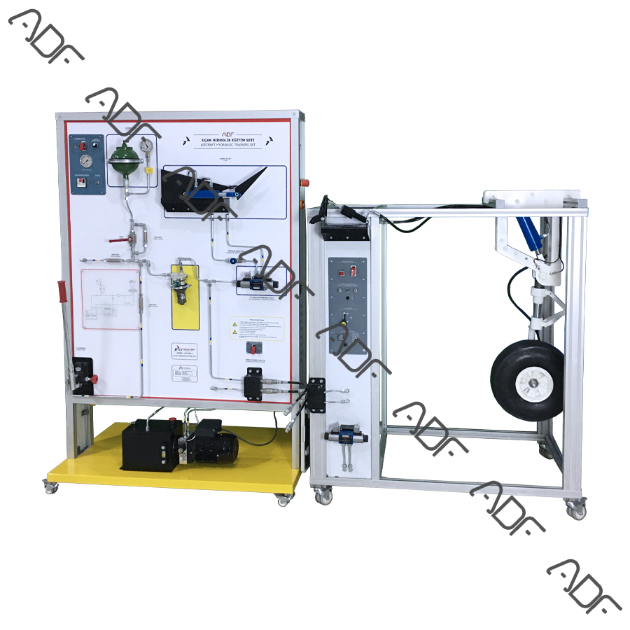
HYD-100A Landing Gear Module for offers effective hands-on training for aircraft landing gear system maintenance trainees.

It assures that technicians are trained to maintain the landing gear system in the best way possible and in accordance with safety standards. It displays the landing gear mechanism as found in actual aircraft. This trainer is designed to represent a landing gear system. It contains all components and assemblies of an actual hydraulic landing gear system.

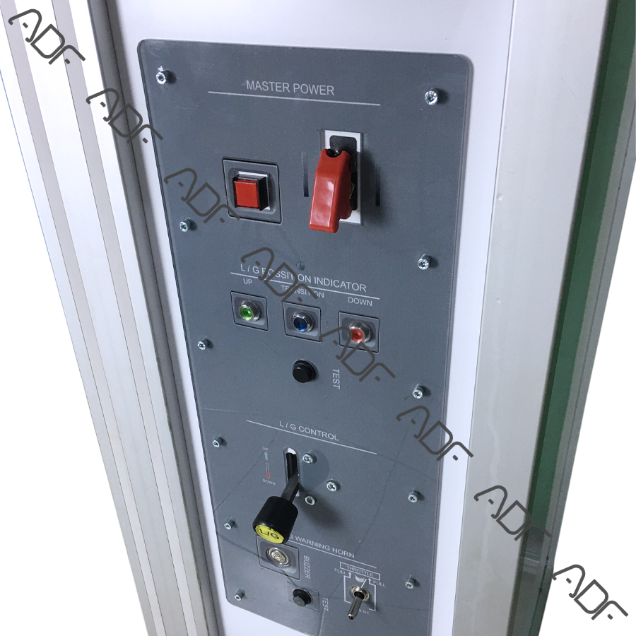
Model HYD – 100A features complete wheel and tire assembly with hydraulic brake system, including master cylinder and brake pedal. The control unit includes control throttles for landing gear and hydraulic flap operation. Indicators demonstrate show up, down, and in-transition conditions. A throttle warning horn is also mounted on the control panel.

This model comes mounted on a mobile stand to provide a clear view from all directions.

Features:

  • Hydraulic Landing Gear System
  • Wheel housing damper.
  • Hydraulic Flap System
  • Hydraulic Brake System
  • Aircraft Wheel System
  • Hydraulic System Control
  • Lower ECAM/EICAS
  • Master Caution System
  • Aural warning Horn Panel System
  • Hydraulic Landing Gear Trainer able to display the landing gear operating system of a regular aircraft.
  • Digital sensor data and switch states used in the set.
  • Throttle lever with associated components complete the warning circuit of gear up warning horn.
  • The accumulator and the hand pump be able to control the landing gear.
  • Wirings on the trainer are connected via terminals.
  • Wires should have clear identification labels for each wire.
  • All wires should be coded and labeled for troubleshooting.
  • Instructor’s panel for Fault Insertion

Components:

  • Electrically Driven Hydraulic Pump
  • Hydraulics Filter
  • Flap/Aileron control solenoid
  • Emergency Hand Pump
  • Hydraulic Fluid Reservoir
  • Hydraulic Accumulator with automatic filling system
  • Hydraulic System analog pressure gauge
  • Valve pressure sender
  • Hydraulic System Pressure sender
  • Hydraulically Operated Landing Gear Mechanism
  • Drain Valve
  • Hydraulic Actuating Cylinder for Landing gear
  • Hydraulic Actuating Cylinder for Landing gear door
  • Check valve
  • Hydraulic System analog pressure gauge
  • Hydraulic System Pressure sender
  • Brake pressure gauge
  • Hydraulic Sequencing System and operate
  • Hydraulic Flap System
  • Hydraulic flap Actuating
  • Flap Position Sensors
  • Flap control switch
  • Cutaway or Mock-up Flap
  • Aircraft Tire Assembly (6 or 8 inch)
  • Aircraft Tire
  • Aircraft Wheel
  • Aircraft Brake disk
  • Aircraft Brake Plate
  • Aircraft Brake caliber
  • Hydraulic Brake Components
  • Aircraft Brake master cylinder
  • Park brake
  • Brake Fluid Reservoir
  • Aircraft Brake Pedal
  • Brake Hose
  • Throttle Lever (TQ)
  • Control Panel
    • Circuit brakers
    • Aircraft Circuit breaker lockout
    • Lockable Landing gear control lever
    • Power Panel
    • Aircraft Master Caution and aural warning Horn Panel
    • Aircraft Landing gear control panel
    • Landing gear status lamp
    • Test button
    • Lockable Flap control panel/lever (pull able)
    • Lockable speed brake control panel/lever (push able)
    • Landing Gear door control lamp
    • Energy Lamp
  • Lower EICAS or ECAM (7 or 10 inch)
    • Landing gear position
    • Landing door position
    • Pressure gauge
    • Sensors status
    • Landing gear system control
    • Throttle Lever Position
    • Speed brake position
  • Other
    • Ten (10) otters for aircraft tire
    • One (1) Analog tire pressure gauge for aircraft tire
  • The system mounted on a metal/aluminum mobile stand.
  • Metal/aluminum frame with 4 wheels. 2 of 4 wheels are lockable.
  • Training video for teachers
  • Delivered fully assembled tested and ready to operate
  • Colored Ultraviolet printing method on aluminum composite panel

Documentation:

  • User’s Manual
  • Study Guide
  • Instructor’s Guide
  • Flow Diagrams
  • Components Diagrams

Power Specs

  • Electrical box
  • Residual current device
  • Emergency Button
  • Energy Signal Lamp
  • 110 VAC 60 Hz or 220-240 VAC 50 Hz