KAYMAZ&OTOMATİK FREN SİSTEMİ İKİ TEKERLEKLİ EĞİTİM SETİ V.2

SKT 100V KAYMAZ&OTOMATİK FREN SİSTEMİ İKİ TEKERLEKLİ EĞİTİM SETİ V.2

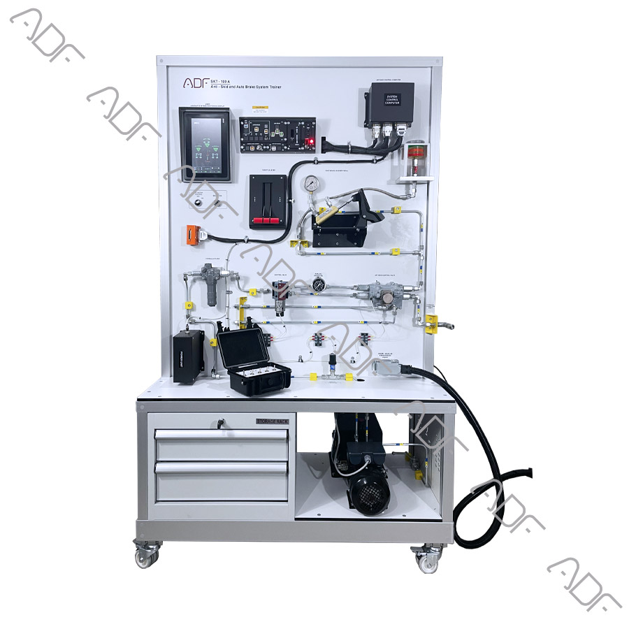
Our Anti-skid and Auto Braking System trainer is designed to represent the anti-skid braking system that is one of the most essential components of modern jet aircraft.

This training set gains more importance as the need for training maintenance technicians in this area keep increasing. Hands-on training provided by this set ensures that trainees not only comprehend the theory, but they are also well prepared in practice to maintain the anti-skid braking system. Anti-skid and Auto Braking System Training Set includes a typical hydraulic brake system as well as the anti-skid assemblies and components.

This training set contains two wheels.

Features:

  • Understanding fundamentals of aircraft auto-brake/anti-skid and its components.
  • Anti-skid and auto-brake system able to work together and independently
  • Non operations of auto-brake scenario are implemented
  • Operations of auto-brake scenario are implemented
  • Take off scenario is implemented
  • Landing scenario is implemented
  • Auto-brake scenarios is implemented
  • Rejected take off scenario is implemented
  • Some of Trainer Functions
    • Auto-brake function
    • Anti-skid function
    • Food brake function
    • Rejected take off function
    • WOW switch function
    • Brake fan function
    • Pump’s fault function
    • ECAM functions
    • Single chime functions
    • Master caution functions
    • Master warning functions
  • Some of Trainer Processes
    • Take-off process
    • Landing process
    • Anti-skid fault process
    • System test process
  • Some of Trainer Cases
    • Brake hot
    • Park brake fault
    • Hydraulic fault
    • Auto brake fault
  • Instructor’s panel for Fault Insertion

Components:

  • Control Panel
    • Aural warning horn
    • Master warning resettable illuminated pushbutton
    • Master caution resettable illuminated pushbutton
    • Auto brake – low illuminated pushbutton
    • Auto brake – medium illuminated pushbutton
    • Auto brake – max illuminated pushbutton
    • Auto brake – RTO illuminated pushbutton
    • Auto brake – disarm instrument
    • Anti-skid INOP instrument
    • Brake fan control illuminated pushbutton
    • Brake fan hot instrument
    • Nose landing gear instrument light
    • Left wing landing gear instrument light
    • Right wing gear instrument light
    • Landing gear unlock instrument light
    • Hydraulic pump control illuminated pushbutton
    • Hydraulic pump fault instrument light
    • Three (3) aircraft circuit breaker
    • Guarded master power switch
    • Master power lamp
    • Lockable Landing gear control lever
  • AC engine on/off switch
  • Air/ground switch
  • Skid simulation panel
  • 10” inch screen (like EICAS or ECAM)
    • Landing gear position
    • Landing door position
    • Numeric pressure value
    • Sensor’s status
    • Anti-Skid/Auto-Brake position status
    • Numeric Simulated air speed value
  • Electronic Control Box (Antiskid Control Computer)
  • Antiskid Valve
  • TQ – throttle quadrant
  • Electrically Driven Hydraulic Pump
  • Hydraulics Filter
  • Hydraulic Fluid Reservoir
  • Hydraulics tank Drain Valve
  • Check valve
  • Brake fan
  • 0-100 bar Hydraulic System analog pressure gauge
  • 0-100 bar Hydraulic System Pressure sensor
  • Aircraft landing gear module
    • Two (2) pieces Aircraft Tire
    • Two (2) pieces Aircraft Wheel
    • Two (2) pieces Aircraft Brake system
    • Two (2) pieces AC motor for turning the wheels
    • Plexiglass cover
  • Aircraft foot Brake Pedal
  • Aircraft foot Brake master cylinder
  • Brake microswitch
  • Two (2) pieces AC motor for turning the wheels
  • Two (2) pieces AC motor driver
  • Fault & instructor port
  • Lockable Fault & instructor box
  • The system mounted on a metal/aluminum mobile stand.
  • Metal/aluminum frame with 4 wheels. 2 of 4 wheels are lockable.
  • Training video for teachers
  • Delivered fully assembled tested and ready to operate
  • Colored Ultraviolet printing method on aluminum composite panel

Documentation:

  • User’s Manual
  • Study Guide
  • Instructor’s Guide
  • Components Diagrams

Power Specs

  • Electrical box
  • Residual current device
  • Emergency Button
  • Energy Signal Lamp
  • 110 VAC 60 Hz or 220-240 VAC 50 Hz

Dimensions and weight

  • Height: 200cm  Width: 140cm   Depth: 85cm
  • Weight: 150kg