KABİN BASINÇLANDIRMA EĞİTİM SETİ

CPS 100A KABİN BASINÇLANDIRMA EĞİTİM SETİ

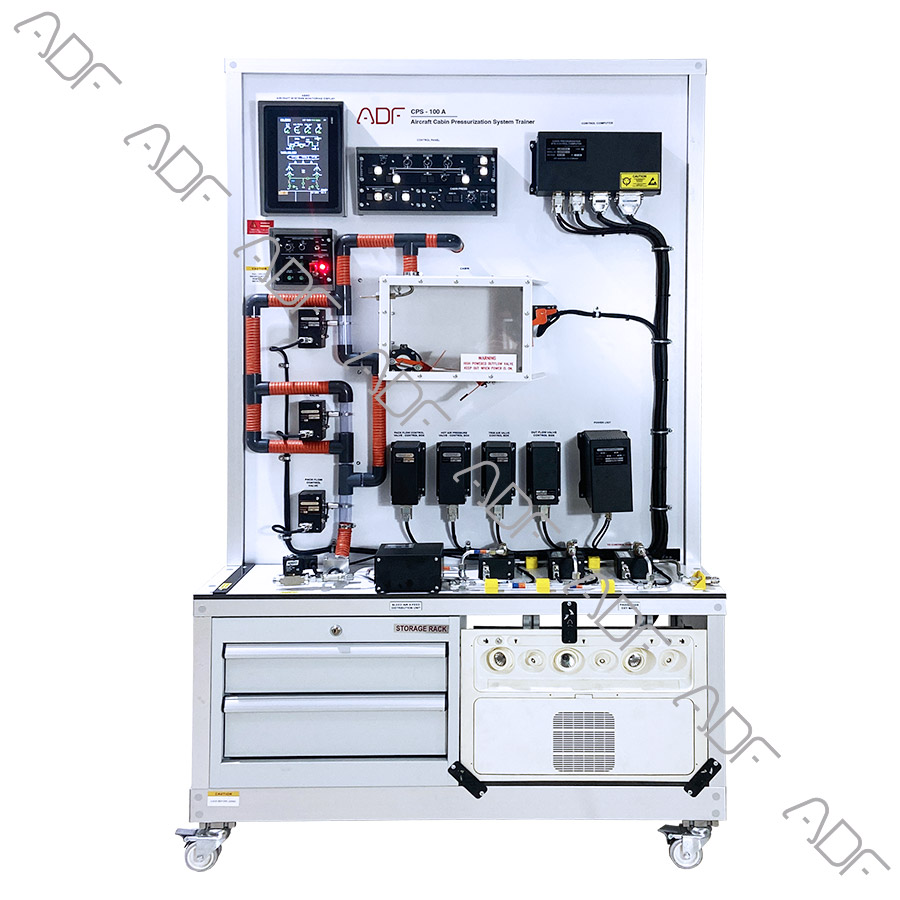
The Cabin Pressurization trainer demonstrates how an aircraft cabin pressurization and air conditioning system function.

The compact construction of the set allows trainees to conceive the system as understanding the connection between the various parts of the system in regulating the cabin environment.

The trainer includes two chambers simulating altitude and cabin pressure.

The vacuum simulating chamber is able to simulate up to roughly 0 – 40,000 ft.

  • Understanding fundamentals of aircraft Cabin Pressurization and its components.
  • The set is functional and configured like a typical aircraft Cabin Pressurization system.
  • The trainer include the following panels that will work functionally.
    • Aircraft Cabin Pressurization panel
    • Aircraft air condition panel
    • Aircraft auto-pilot panel
    • Test panel
    • Master power panel
    • Master caution panel
  • Two transparent cabin in the training set to simulate the interior of the cabin.
  • 2 outflow valves, 1 negative pressure safety valve, and positive pressure safety valve (as a substitution) are in the transparent cabin.
  • Out Flow Valves are engine controlled.
  • The valves in the cabin pressurization system operate automatically during the take off and landing.
  • Cabin pressurization valves are both controlled manually and automatically.
  • The trainer is able to perform full automatic take off and landing.
  • Indicators, panels and valves work simultaneously in landing and take-off simulations.
  • Take off and landing simulations are controlled from the autopilot panel.
  • Vertica speed and altitude are determined and selected during take-off and landing.
  • Valve failures are easily observed on gauges and panels.
  • PACK, BLEED, PACK FLOW and TEMPERATURE selections are made at the air condition panel.
  • LDG elevation, MODE SELECT, MAN V/S CONTROL and DITCHING are done at the cabin pressurization.
  • The selections made in the panels are visible on the screen.
  • Wirings on the trainer are connected via terminals.
  • Wires should have clear identification labels for each wire.
  • All wires should be coded and labeled for troubleshooting.
  • Instructor’s panel for Fault Insertion
  • PSU( Passenger Service Unit)
  • 10 inch Lower ECAM
    • Vertical speed indicator
    • Altimeter indicator
    • Cabin Altimeter
    • Cabin pressure
    • Air pressure
    • Differential pressure
    • Status area
    • Flow status
    • Pack flow status
    • Bleed status
    • Auto pilot status
    • Pressurization mode
    • Temp
    • Air/ground
  • Min 2 Outflow valve
  • Min 2 outflow control computers
  • Aircraft Cabin Pressurization panel
    • Man V/S Control Switch
    • Mode selector
    • LDG ELEV Knop
  • Aircraft air condition panel
    • Pack-1 control
    • Pack-2 control
    • ENG 1 Bleed
    • ENG 2 Bleed
    • APU Bleed
    • Pack Flow Selector
  • Aircraft auto-pilot control panel
    • Vertical Speed Selector
    • Altitude Knop
    • Control Siwitch
  • Terminals
  • Master power panel
  • Master power light
  • Master caution panel
  • Aural warning horn
  • Test panel
  • Circuit Breakers,
  • LAN output
  • Fault Panel for instructor.
  • Outflow valve control boxes
  • Outflow valve terminals
  • Vacuum chamber (altitude simulator)
  • Cabin pressure chamber (cabin simulator)
  • Regulator (simulates air to cabin)
  • Cabin pressure sensor
  • 24 VDC power supply

 ATA Chapters

  • The system mounted on a metal/aluminum mobile stand.
  • Metal/aluminum frame with 4 wheels. 2 of 4 wheels are lockable.
  • Training video for teachers
  • Delivered fully assembled tested and ready to operate
  • Colored Ultraviolet printing method on aluminum composite panel

Documentation:

  • User’s Manual
  • Study Guide
  • Instructor’s Guide

Power Specs

  • Electrical box
  • Residual current device
  • Emergency Button
  • Energy Signal Lamp
  • 110 VAC 60 Hz or 220-240 VAC 50 Hz

Dimensions and weight

  • Height:    Width:    Depth: