Features:
- Understanding fundamentals of aircraft Marker Beacon and its components.
- 0-10A DC current meter and 0-30 V DC voltmeter
- Reception test
Components:
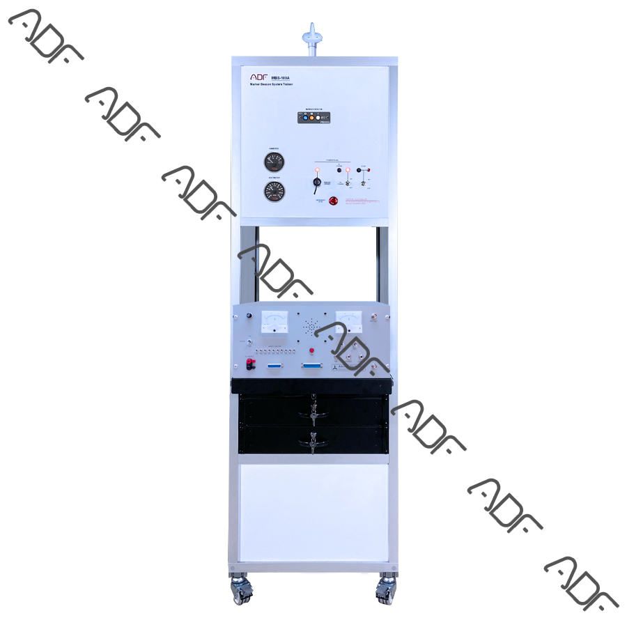
- MB (Marker Beacon panel)
- Indicator lamp.
- MB antenna with coaxial connector
- Dc Power Box
- Aircraft Circuit Breaker
- Circuit Breaker Lockout
- Audio jack
- Volume control
- Speaker
- HI/LO sensitivity switch
- 20A power supply
- Current and voltage meters
- Assembled and wired according to aeronautical regulations
- Aeronautical standard connectors and jackets
Components Technical Specs
- MB Device General Specs
- 75MHz Crystal Controlled
- Sensitivity:
- Low: 1000 mVolts (Hard) (360 to 570 mV soft)
- High: 200 mVolts (Hard) (130 to 200 mV soft)
- Selectivity: -6 dB at ±10 kHz, -40 dB at ±120 kHz
- External Lamp Output: 7.5 (±4 VDC unloaded, at maximum brightness) VDC positive when active, max. current 125 mA per lamp output
- MM Sense: Active high (4.5 ± 1.0VDC)
- Output impedance: 510 W
- Audio Output: 38 mW <5% THD typical
Optional
- NAV/COM Ramp Tester
- Output Power;
- ADF = -12 +/-3 dbm
- VOR= -10 +/-3 dbm
- ILS Localizer= -10 +/-3 dbm
- ILS GS = -17 +/-3 dbm
- ILS MKR = -15 +/-3 dbm
- DME = -12 +/-3 dbm
- TXPDR = -12 +/-3 dbm
- VOR radial accuracy; +/- 1 deg
- ILS localizer DDM accuracy; +/- 15%
- ILS glide slope DDM accuracy; +/- 15%
- DME accuracy; +/- 0.1NM
- Transponder specs;
- PRF 235+/-5 Mode A, C 50 +/-2 Mode S
- P2 level equal P1 +/- 0.1 dbm
- P2 position 2 +/-0.01 uS from P1
- P3 position 8 +/- .01uS or 21 +/- 0.02uS Rel to P1
- Pulse width 0.8 +/-0.01uS P1, P2, P3
- Frequency 1030 MHz Tx, 1090 MHz Rx, +/- 2.5ppm
- Reply % 0 to 100% displayed +/- 0.5%
- Reply window 2.5 to 3.5uS F1 from P3
- Pulse Width reads out to +/- 50nS resolution
- X Data Pulse Must=0 for good read
- SPI Displays ID message
NOTE: Avionics devices brand/model and some technical specs can be change due to market availability.